Steering Gear Control & Operation System | Electropneumatic S.A.
System Overview
The Electropneumatic’s Professional Steering Gear Control & Operation System (SGCOS) is a trustworthy Marine Technology developed for transmitting orders from the vessel’s navigation bridge to the steering gear power actuating system. It is a Programmable Electronic System (PES)/Computer-Based System (CBS) suitable for steering single or dual-rudder vessels which is compatible with the most power actuating steering systems (solenoid operated valves, frequency-controlled
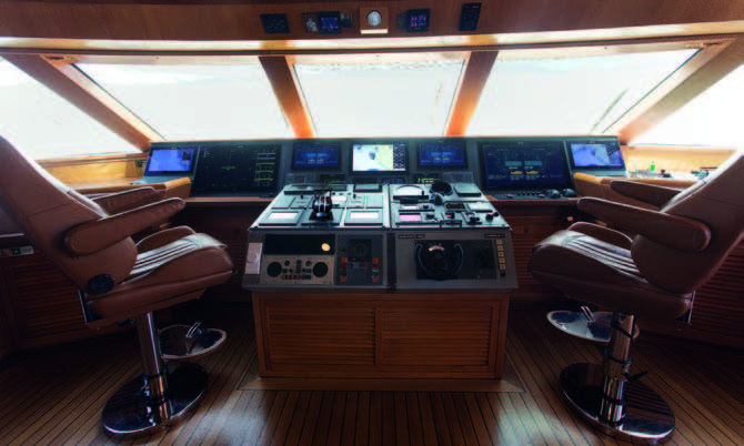
pumps/motor). The positions for handling the Steering Control & Operation System can be located in the center of the bridge, on the bridge wings, on the top bridge deck (for luxury yachts) and locally in the steering gear room.
The system is designed and constructed to meet the applicable Rules of the major Maritime Classification
Societies .
System Lay Out
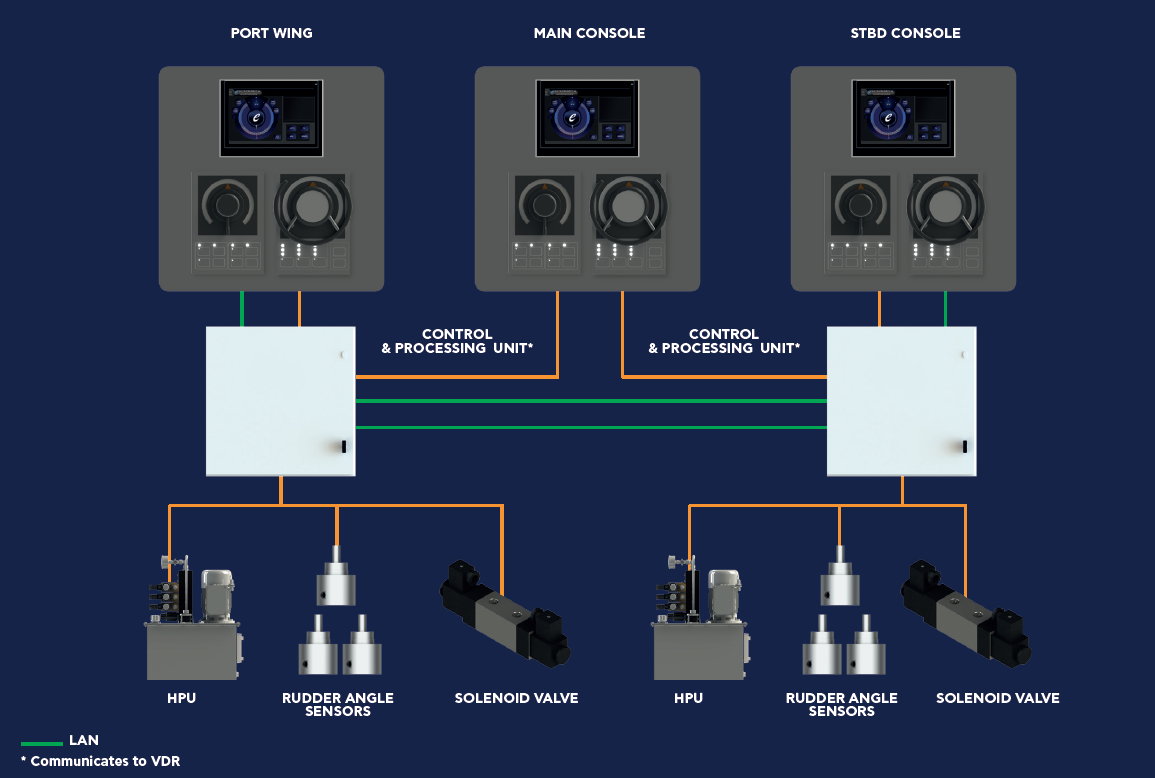
The Electropneumatic’s Professional Steering Gear Control & Operation System is built up with the following main units:
- Levers (FU and NFU)
- Main processing & control units
- Remote propulsion control stations (with sensitive touch-screen operator panels)
All the above units are built-up with state-of-the-art and asbestos‐free components (CPU’s, I/O Modules, sensitive touch-screen operator panels, etc.), which are constructed by well-known manufacturers, as well as they are suitable for the intended use and furnished with Marine Type Approval Certificates or Product Design Assessment Certificates from the major Classification Societies (DNV-GL, Lloyds Register, ABS, etc.) and they shall be in the market for the next years.
Typical Steering Gear Control & Operation System arrangement is illustrated here below. Final configuration based on customer requirements.

System Key Features
Multiple redundancy levels design to ensure full control of steering is maintained in any malfunction situation. To implement this capability the system consists of two control systems, Follow Up / Non-Follow Up (FU / NFU), which are independent in all respects.
System Key Features
Multiple redundancy levels design to ensure full control of steering is maintained in any malfunction situation. To implement this capability the system consists of

two control systems, Follow Up / Non-Follow Up (FU / NFU), which are independent in all respects.
Power supply for each control system by separate circuits.
Control System Override:
- Control system disconnection from the power when local control
is to be used. - Capability of complete disconnection of all stations, except the one in use.
- Audible alarm (continue to sound until it is acknowledged) and visual alarm on the touch-screen operator panel at the primary steering station in case the automatic autopilot override fails to respond when the manual helm order is 5 degrees (or greater) of rudder angle or immediately activated upon automatic
autopilot override actuation.
Computer-based system failures alarm on the touch-screen operator panel at the bridge steering control station.

Duplicated electric components of the steering gear control system (except from the steering wheel and steering levers for FU and NFU).
Built-in reliability with PROFINET and MODBUS Technology.
System Security arrangements are provided to prevent unintentional or unauthorized access to functions or alteration of configuration, programs or data by unauthorized personnel.
System’s essential programs and associated memory data is stored in non-volatile or volatile memory with a secure uninterruptible power supply (UPS).
Comfortable operation with take-over or give-over function of steering control positions (Navigation Bridge, Wings, local control panel).
Easy integration with Auto Pilot Unit.
Capable of connecting to the Voyage Data Recorder (VDR) and Dynamic Position System
Displays and alarms of monitored parameters required by Class Societies’ Rules, on the sensitive touchscreen operator panels on navigation bridge and in steering gear compartment and/or Engine room control station, as applicable:
- The set point and feedback indications
- The rudder angle indicator
- The power unit motor running
- Visual and Audible Alarms (Power Supply Failure, Power unit motor overload, hydraulic oil reservoir low level, auto-pilot failure, Hydraulic lock, earth fault on AC and DC circuits, deviation between rudder order and feedback, etc.)
- Steering mode in operation (Autopilot / FU / NFU
- Control Panel in operation (Navigation Bridge, Wings, local control panel)
Control Panels with manual or automatic dimming control.
Self-monitoring function that presents an alarm at the touchscreen stations whenever any incorrect operation or abnormal condition occurs.
Easy installation-maintenance.


